

Jumpers and Test Points
Solder Jumpers (JPx)
Jumper
Default
Function
Description
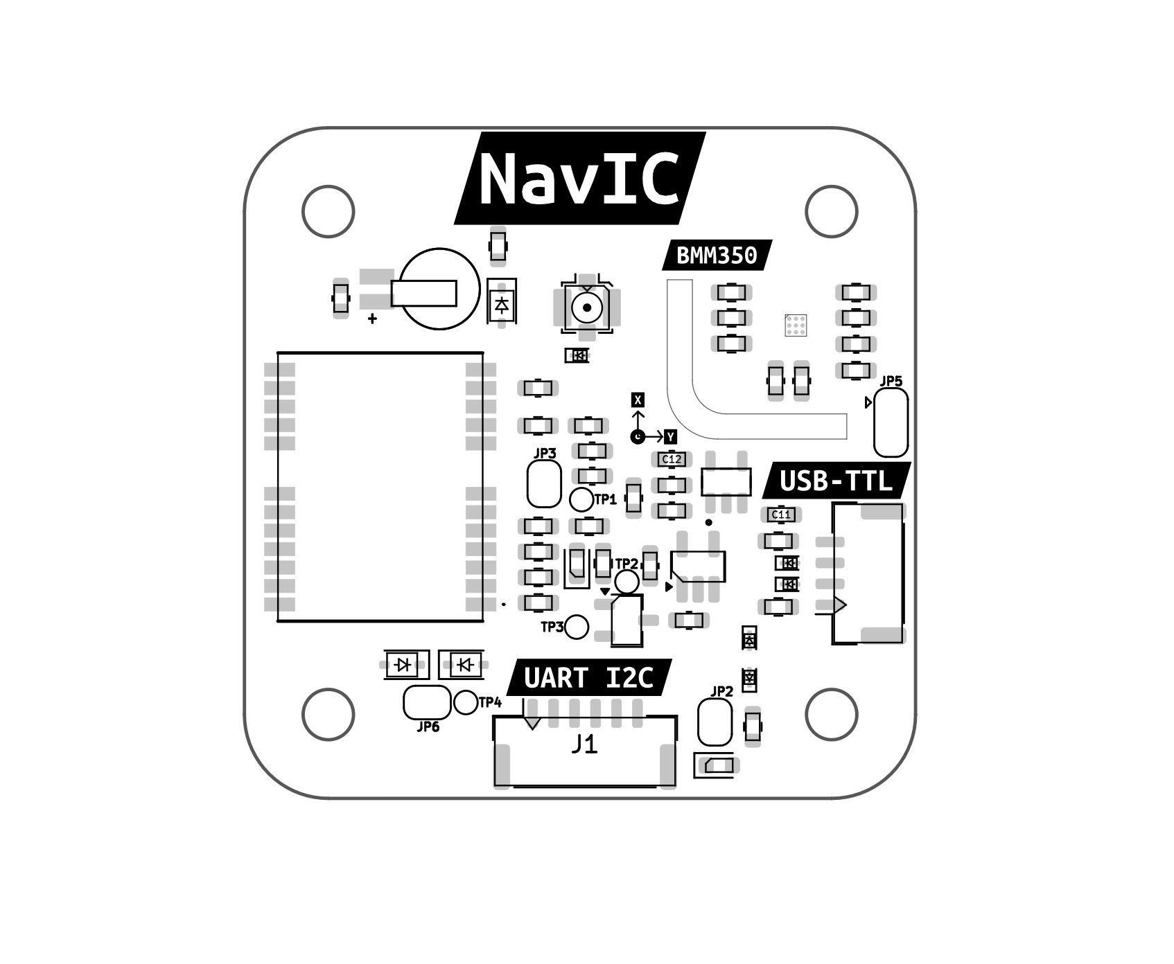
JP2
Bridged
Disable Power LED
Disconnect this jumper to disable the onboard power LED. Useful for power saving or stealth applications.
JP3
Bridged
Disable PPS LED
Disconnect to turn off the LED that blinks with PPS signal.
JP5
GND via 4.7kΩ
Magnetometer I²C Address Select
3-way jumper. Default connects ADSEL to GND via 4.7kΩ → I²C address 0x12. Bridge the alternate pad to 3.3V via 1kΩ to change to 0x13 (per BMM350 datasheet).
JP6
Open
Bridge UART/I²C 5V ↔ USB-TTL 5V
Used to connect or isolate the 5V rail between GPS port and USB-TTL input. Bridge only if both share power safely.
Test Points (TPx)
Test Point
Signal
Description
TP1
Event Pin
GNSS event input (used for time-stamping or external edge-triggered events).
TP2
PPS Output
1Hz Pulse Per Second signal output from the GNSS module.
TP3
SafeBoot
Used to pull the GNSS module into firmware recovery (SafeBoot) mode.
TP4
VCC (after protection diode)
Measures input voltage after the reverse-polarity protection diode.